
Standing Seam Metal Roof Details: Key Connections and Drawings
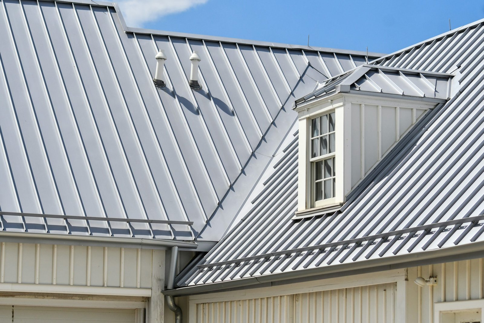
Standing seam metal roof details are the drawings and connection specifications that show how panels meet the roof edge, ridge, valley, wall, and penetrations. These junctions determine how water drains, how panels move with temperature, and how the roof connects to the structure. A useful details package is specific to the panel manufacturer, roof slope, substrate, climate, and project—not a generic sketch copied from another roof.
This homeowner guide explains the main details to look for in a standing seam metal roof details PDF, what each drawing should communicate, and what to ask a contractor or designer before fabrication. It is an orientation guide, not a substitute for engineered project documents or the selected manufacturer’s installation instructions.
What a standing seam detail drawing should show
A clear detail identifies the panel profile and material, seam type, clips, fasteners, underlayment, substrate, flashing, closures, and the direction water travels. It should name the roof slope and show dimensions and attachment locations. A detail that simply labels a line “metal roof” leaves important questions unanswered: how is the panel held down, where can it move, and how is the edge protected from wind-driven rain?
Standing seam is a family of systems. Some panels use concealed clips; others have different seam geometries or attachment methods. Clip spacing and fastening depend on the tested system, design loads, panel width, support spacing, and substrate. Do not use a detail for one profile to order or install a different profile. The Metal Construction Association and manufacturer manuals provide system-specific guidance; SMACNA’s inspection resources discuss seams, flashing, ridges, valleys, penetrations, and other sheet-metal conditions.
Eave and rake: start and side edges
The eave is the lower edge where water leaves the roof. A drawing should show the panel’s lower termination, cleat or hem where required, edge flashing, underlayment sequence, and the route into a gutter or over a drip edge. The detail should prevent water from reaching the roof deck while allowing the panel system to be installed in the prescribed order.

The rake is the sloped edge at a gable. Rake trim must suit the panel profile and roof assembly. Check that the drawing identifies how trim is supported and secured, how the panel is captured, and how the end is closed against wind-driven water. A small gap or improvised sealant bead should not replace a designed closure or flashing component.
Ridge and hip: the high points
At a ridge, panels from opposing roof slopes meet. The detail should identify the ridge cap, closures, panel termination, and whether the ridge is vented. A vented ridge needs a compatible ventilation path and weather protection; a non-vented cap has different components. Do not assume a ridge cap itself provides ventilation. Hip details similarly need a cap shaped and fastened for the intersecting planes, with closures that match the panel ribs.
Look for the required clearance and movement allowance. Long metal panels expand and contract as temperature changes, so the system must use the specified clips, fixed points, and end details. Avoid replacing a sliding clip with a fixed fastener or locking a panel at multiple locations unless the manufacturer’s tested instructions call for it.
Valleys and roof-to-wall intersections
A valley carries runoff from two roof surfaces, so it concentrates water. The drawing should show the valley pan, panel setbacks or folds, underlayment, support, and how water is kept from running beneath cut panel edges. The required width and configuration vary with roof geometry, slope, expected flow, and the roofing system. See our separate guide to metal roof valleys for more on water-shedding choices.
At a sidewall or headwall, step or continuous flashing must integrate with the wall’s water-resistive layer and the roof panels. A good detail shows the sequence: which layer laps over which, where counterflashing terminates, and how the panel rib is accommodated. At a dormer, chimney, or skylight, the intersection should be drawn for that specific obstruction rather than solved with sealant alone.

Penetrations, curbs, and attachments
Plumbing vents, chimneys, skylights, and mechanical curbs interrupt the panels. Each penetration needs a compatible flashing assembly and a plan for water to flow around it. On a standing seam roof, attachments may clamp to seams or connect through a flashed penetration; the allowed method depends on the roof profile and the accessory manufacturer. Do not drill through a panel or seam based on a generic drawing without confirming the approved detail.
Solar attachments deserve special coordination. Our article on solar panels on metal roofs explains why the roof manufacturer’s requirements, attachment design, and warranty terms should be reviewed together. Likewise, the system’s material and installation scope is easier to compare when panel profile, underlayment, trim, and flashing are listed clearly.
Thermal movement, clips, and fasteners
Metal panels change length as temperature changes. Many concealed-clip systems are designed to accommodate movement, but the details must show where fixed points are located and where clips allow travel. Clip type, spacing, and fastener selection are not interchangeable across projects. They depend on panel engineering, wind uplift, snow or other loads, support material, and the manufacturer’s tested assembly.
Ask the designer or installer to identify the specified fasteners and substrate, not just “roofing screws.” Check whether fastener heads, washers, and corrosion protection are compatible with the panel metal and environment. Mixed metals can corrode in some conditions. The material schedule and manufacturer instructions should address compatibility and coastal or industrial exposure when relevant.
How to review a details PDF before work begins
- Confirm the panel manufacturer, profile, seam type, thickness, finish, and project address or roof area.
- Check that the drawings cover eave, rake, ridge, hip, valley, wall, and each roof penetration used on the building.
- Look for clip type and spacing, fixed points, fastener specifications, substrate, and the intended movement direction.
- Trace the water path on every transition and check that upper layers lap over lower layers.
- Confirm ventilation, underlayment, ice or weather protection, and gutter integration where applicable.
- Verify that the details match the product’s current installation manual and project engineering.
- Ask who resolves conflicts between the architectural drawings, manufacturer details, and local code.
For small residential work, the manufacturer may provide standard details, but a complicated roof can require project-specific drawings. A professional should confirm that the selected assembly meets the building’s design conditions. The International Building Code and local amendments may apply; requirements vary by jurisdiction, roof slope, building type, and exposure. Never treat a downloadable PDF as approval for a particular site unless the designer or building official has accepted it.
Common detail problems to flag
Watch for drawings that omit the panel profile, show an incompatible trim, rely on sealant as the only water barrier, or leave the valley and wall transitions undefined. Another red flag is a clip schedule copied from a different building without checking wind loads and support spacing. Details should be coordinated before panels are cut; late field changes can create leaks, trapped water, visible patches, or warranty disputes.
Ask for the current manual and product data sheets along with the drawing set. Keep those documents with the contract, inspection notes, and closeout package. Photograph concealed conditions before they are covered, where practical. If a leak appears later, the detail set helps a roofer trace the path from the visible symptom back to the likely transition. Our guides to metal roof leaks in heavy rain and roof pitch and drainage offer related checks.
Frequently asked questions
What does a standing seam roof detail PDF include?
It should show system-specific connections such as eaves, ridges, valleys, wall transitions, clips, fasteners, underlayment, and penetrations. The exact set depends on the building and selected panel system.
Can I use a generic standing seam detail for my project?
Use generic drawings only for orientation. Installation must follow the selected manufacturer’s current details and project requirements, because profiles, clips, loads, and substrates differ.
Why do standing seam panels need movement allowance?
Metal changes length with temperature. The specified clips and fixed points allow the panel to move as designed while keeping it attached to the roof structure.
How should a standing seam roof valley be detailed?
The design should define the valley pan, panel termination, underlayment, support, and water path. Dimensions and installation sequence must suit the roof geometry and the selected system.
Sources
- SMACNA, Architectural Sheet Metal Inspection Guide
- SMACNA Technical Standards and CAD resources
- UFGS 07 61 15, Aluminum Standing Seam Roofing specification
Images: Unsplash, Earl Wilcox, J A C K, and chris robert, used under the Unsplash License.
